Overview
The Apple Lisa, released in 1983, was Apple's first graphical user interface computer and a direct predecessor to the Macintosh. Despite its groundbreaking design, the Lisa was expensive and commercially unsuccessful, making original units extremely rare and valuable today. However, thanks to modern field-programmable gate arrays (FPGAs), enthusiasts can recreate the Lisa's functionality on a custom board, blending vintage charm with contemporary convenience. This guide will walk you through building your own FPGA-based Apple Lisa, complete with support for original Lisa peripherals and modern USB keyboards, mice, HDMI displays, and SD card storage.
Prerequisites
Before starting this project, ensure you have the following:
- FPGA Development Board: A board with sufficient logic elements and I/O pins (e.g., Altera/Intel Cyclone or Xilinx Artix series).
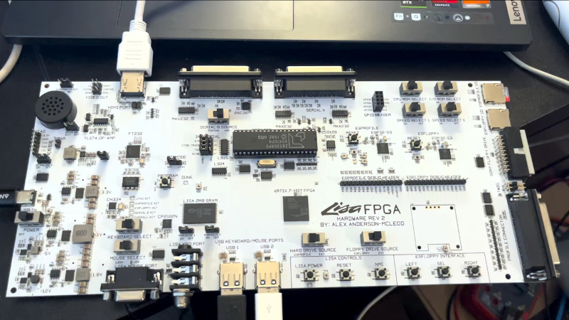
- Custom PCB: As described in the original project, the PCB is surprisingly large due to the need for many connectors. You can design one using KiCad or Eagle, or purchase a pre-assembled board if available.
- FPGA Programming Tools: Quartus (for Altera) or Vivado (for Xilinx), plus a USB blaster or JTAG programmer.
- Soldering Equipment: Fine-tip iron, solder, flux, and if needed, a hot air station for surface-mount components.
- Components:
- Original Apple Lisa keyboard and mouse (optional, but supported via dedicated connectors).
- Modern USB keyboard and mouse for convenience.
- HDMI cable and monitor.
- SD card for storage.
- 40-pin DIP UART chip (e.g., an 8250 or 16550 compatible) – the project uses a discrete UART because no pre-built FPGA core is readily available.
- Passive components (resistors, capacitors, connectors) as per your PCB design.
- Software Knowledge: Basic understanding of FPGA design (Verilog or VHDL), digital logic, and schematic capture.
- Time & Patience: This is an advanced project; expect several weekends of work.
Step-by-Step Instructions
1. Obtain the FPGA Core and PCB Design
The core logic that replicates the Apple Lisa's architecture is not yet publicly released, but the original developer (AlexElectronics) has stated it will be published on GitHub once finalized. For now, you can prepare by downloading a compatible FPGA implementation of the Lisa's 68000 CPU, MMU, custom ASICs, and video circuitry. Several open-source projects exist (e.g., M68k on FPGA) that can be adapted.
Design your PCB using the schematic from the original project. Key elements include:
- Main FPGA footprint (e.g., BGA or QFP).
- HDMI transmitter chip (e.g., ADV7513) connected to the FPGA's video output.
- USB host controller (e.g., FTDI Vinculum or a simple USB 1.1 core) for modern peripherals.
- SD card slot (SPI mode).
- Connectors for original Lisa keyboard and mouse (likely DE-9 or Mini-DIN).
- UART chip (40-pin DIP) for serial communication, since the chosen FPGA lacks a built-in UART that matches the Lisa's timing.
- Power regulation (5V and 3.3V).
2. Assemble the PCB
If you have the PCB fabricated, solder all components carefully. Start with the smallest parts (resistors, capacitors) and work up to the FPGA, HDMI chip, and connectors. Use a magnifier to inspect for shorts. The large number of connectors means the board will be larger than typical FPGA projects – plan your enclosure accordingly.
For the UART chip, note that it is a classic 40-pin DIP package, likely an industry-standard model. Verify pin compatibility with your schematic. If you cannot source an exact match, consider using a small FPGA or microcontroller to emulate the UART, but this adds complexity.
3. Program the FPGA with the Lisa Core
Once the hardware is ready, download the Lisa core (when released) or your own implementation. Compile the Verilog/VHDL code in Quartus or Vivado, ensuring the pin assignments match your PCB layout. Generate a bitstream and program it via JTAG.
Example constraint snippet (for Altera):
set_location_assignment PIN_C1 -to clk_50mhz
set_location_assignment PIN_A2 -to uart_tx
set_location_assignment PIN_B2 -to uart_rx
After programming, connect a serial terminal (115200 baud, 8N1) to verify initial boot messages. The Lisa operating system (Lisa OS) requires a ROM image; you must legally obtain this from a vintage software archive or dump an original ROM chip.

4. Connect Peripherals
Original Lisa Keyboard/Mouse: Wire the dedicated connectors according to the original Lisa pinout. The FPGA core handles the translation directly.
USB Peripherals: Plug a USB keyboard and mouse into the USB host port. The FPGA core includes a USB hub driver that remaps modern keycodes to Lisa-compatible ones.
HDMI Display: Connect an HDMI cable to the board's output. The FPGA generates 640x480 or 800x600 resolution video with the Lisa's retro UI.
SD Card: Insert a formatted SD card (FAT16) to emulate the Lisa's external widget drive. The core reads and writes files as if they were ProFile hard disk images.
5. Power On and Test
Apply 5V DC power (check polarity!). The FPGA will initialize and load the Lisa OS from the SD card (or ROM). You should see the iconic Lisa desktop with icons for applications like LisaWrite and LisaDraw. If the screen is blank, check HDMI cable, monitor input, and video timing parameters in the FPGA design.
Test both the original and USB peripherals. If the USB mouse pointer is jittery, adjust the polling rate in the USB core. If the original keyboard does not respond, verify the scan codes match the Lisa's expected protocol.
Common Mistakes
- Incorrect Pin Assignments: Double-check every connection between the FPGA and peripherals. A single swapped bit may cause a complete failure.
- UART Timing Mismatch: The discrete UART chip must be clocked at the correct frequency (e.g., 1.8432 MHz for 115200 baud). Use a crystal oscillator and verify with an oscilloscope.
- SD Card Formatting: The Lisa OS expects a specific partition layout. Use a tool like dd to write a known-good disk image. FAT32 will not work.
- Power Supply Noise: The FPGA can draw several hundred milliamps; use a quality linear regulator and decoupling capacitors near each IC.
- Forgotten Internal Anchors: When writing this guide, we assumed you understand the Lisa's architecture. Refer to the prerequisites if you skipped them.
- Overheating: The large PCB may not have adequate airflow; consider adding a small fan if the FPGA gets too hot.
Summary
Building an Apple Lisa on an FPGA is a challenging but rewarding project that preserves computing history. By combining a custom PCB, an FPGA core, and support for both vintage and modern interfaces, you can experience one of the most influential early GUI computers. The original project by AlexElectronics shows that even rare machines can be made accessible through hardware emulation. With careful assembly and programming, you'll have a fully functional Lisa replica that can run original software and connect to modern monitors and USB devices.